Industrial drive engineering with its automated manufacturing processes would be hardly conceivable without electric motors. IGBT semiconductor elements control powerful electrical drives whose connection is realized by way of polymer optical fibres for the required isolation. This solution is space-intensive and sensitive, however. HARTING offers users a new, miniaturized approach here in IGBT control.
The power consumption of the electric motors used as a drive technology can reach several kW or even MW. At constant speeds, their control technology is relatively simple. But the motor speed often needs to be adjustable, which makes the whole thing more complicated immediately.
In the higher power classes such as traction control in trains or ship propulsion systems, the speed is controlled by way of IGBT semiconductors. These are able to switch great loads with very little driving power. The signals required for IGBT control are transmitted by means of polymer optical fibres (POF) because the isolation and voltage requirements to be met are very high. Six IGBT driver boards are currently required per phase 2 to control a three-phase motor. The PO fibres meanwhile realize interference-free and electrically isolated signal transmission.
Especially where locomotives are concerned, IGBTs are provided redundantly so that the controller board can transfer the function to the redundant component and ensure the functionality of the system if an IGBT fails. This is attended by a doubling of the optical transmission distances. The connection between the controller and driver board meanwhile used to be provided by individual fibres in the past. The electro-optical signal conversion takes place in the transceivers of the circuit board, with optical contacts establishing the connection to the fibres. Every optical fibre has an individual port with the transceiver in it on the driver board as well as the controller board. This previous solution meant that all the sending and receiving elements took up a lot of space on the controller board, which made the board unnecessarily large.
Another disadvantage is the fact that the various PO-fibres need to be plugged in at the right places in service calls and in their installation, as every fibre needs to be connected to the driver board and controller board individually. This alignment needs to be done attentively and takes some time and care. The sender and receiver must not be mixed up for correct operation.
To guarantee the quality of the fibre end surface, the cables used are prefabricated, and can also be individually installed by the user on site.
The customarily used optical elements were basically developed for industrial applications with expanded temperature ranges and increased vibrations, but only offer the fibres a simple strain relief. What is also important is that the optical interface needs to be consistently protected from soiling. This even makes protective covers necessary in an unplugged state.
Post-hoc equipment of the controller board with optical elements is also impossible as they are not reflow-capable at this point in time. So if a transceiver breaks, one had to disconnect, replace and reconnect the entire board with all its contacts in the past, which was in turn attended by additional costs and labour.
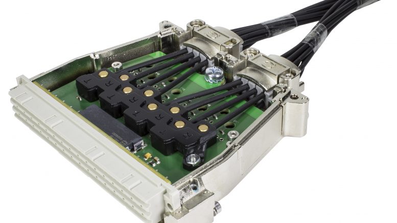
In cooperation with established rail vehicle manufacturers, HARTING has developed the solution of a transmission principle that involves relocating the controller board’s transceivers to a pluggable module and thus integrates the optical interface true to the motto “electrical plugging and optical transmission”.
For the electrical plugging and system housing, HARTING relies on solutions from the DIN 41612 range. The DIN housing is made from die-cast zinc and meets the railway market’s increased requirements for robustness and EMC. It offers the possibility to run the cables straight or angled, and thus integrates an optimal kink-protection and strain relief for the fibres. In addition, the circuit board in the DIN housing is able to accommodate series resistors and decoupling capacitors as required for error-free control of the optical elements and for excluding interferences. The electrical contacts in the DIN 41612 range are also resistant to micro-vibration wear and thus even tested and approved for railway applications.
The active-optical POF module enables the client to connect up to 16 optical channels at the same time on the smallest assembly space. Installation and service can be simplified and abridged as a consequence. HARTING furthermore offers its clients customized systems that are designed and tested in keeping with their requirements. The integration of the optical interfaces in a quickly replaceable plug-in connector additionally makes servicing the controller boards used faster, easier and cheaper.
The system furthermore supports data rates of up to 50 Mbit/s, which will normally not be required, however, thanks to the high edge steepness of the sender elements used. 3.3 and 5 volts are both available as supply voltages here.
In the first step, the new DIN connections will only be installed in the controller boards. The IGBT driver boards will remain unchanged for now to enable an easy transition to the new system. Thanks to this incremental approach, not all the required components will need to be adapted immediately. But the applied principle can be transferred from the controller board to the IGBT driver board in future, also enabling the realization of bi-directional optical plugging and electric transmission there by way of a compact D-sub housing. The result would be the creation of a bilateral active-optical cable for IGBT control. This way, a robust and service-friendly solution from the railway sector can also be adapted in industrial applications in the future.